
i am looking for the electrical size of the sensor i need to do my gsxr swap. i have found tons of different sensors and not real sure what i am looking for. also i have found the magnets for the rotors already but not sure how many i need, I am guessing it depends on the sensor. Most people say 4, but the one done in moto mag has 8?? Any info would help Thanks

wheet493
hall effect sensor for swap??? need help
2 reading
wheet493
Discussion starter
38 posts
·
Joined 2010
- Add to quote Only show this user
i am looking for the electrical size of the sensor i need to do my gsxr swap. i have found tons of different sensors and not real sure what i am looking for. also i have found the magnets for the rotors already but not sure how many i need, I am guessing it depends on the sensor. Most people say 4, but the one done in moto mag has 8?? Any info would help Thanks
4,525 posts
·
Joined 2008
For your 2008 you will need 8 magnets
For the hall effect sensor I used the GS100701 part number 512401 from https://www.jameco.com/webapp/wcs/s...FUZ4WmdpsPojh2fmYHN C5z6KlhYP/+NXpz34pde&ddkey=https:StoreCatalogDrillDownView
For the hall effect sensor I used the GS100701 part number 512401 from https://www.jameco.com/webapp/wcs/s...FUZ4WmdpsPojh2fmYHN C5z6KlhYP/+NXpz34pde&ddkey=https:StoreCatalogDrillDownView
4,525 posts
·
Joined 2008
Gsxr´s speed sensor should do the job, and it uses same plug (to the speedo) as the stock Sv's, which makes things a little bit easier. Early second gen. speedos work with 4 magnets, but later models need 8.
Not quite:
all 05+ require 8; <05 need 4.
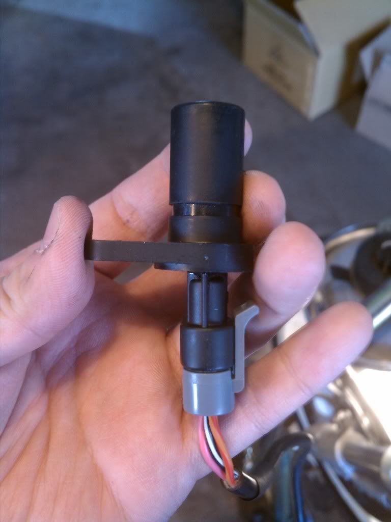
Please re-read the thread it's been said 3 times in 3 pagesSo just to make sure I'm doing this right. I'll be running an 05 GSXR 1000 wheel/rotor setup on my 07 SV. Do I use 4 or 8 magnets? If 4 I just put them in every other hole and if 8 every hole (rotor has 8 holes) using these magnets http://www.leevalley.com/US/wood/page.aspx?cat=1,42363,42348&p=32065 in these holders http://www.leevalley.com/US/wood/page.aspx?cat=1,42363,42348&p=32066 and I'll be using this sensor https://www.jameco.com/webapp/wcs/s...FUZ4WmdpsPojh2fmYHN C5z6KlhYP/+NXpz34pde&ddkey=https:StoreCatalogDrillDownView mounted like the pic above. Wiring the sensor like like this brown = VCC goes to orange/red
blue = Ground goes to black/white
black = output goes to pink
Also anywhere to buy that bracket so I don't have to make it?

948 posts
·
Joined 2006
You should know there are two types of Hall effetc sensor: active and passive. The passive ones detect a passing magnet, the active ones can detect any piece of iron, like a bolt head. I find the active type more convenient since I can use it to pick up the disc bolts, then use a speedo-healer to correct the frequency. I've used ones from a GSXR and from a Ducati, or Mouser sell them.
37 posts
·
Joined 2009
Gsxr´s speed sensor should do the job, and it uses same plug (to the speedo) as the stock Sv's, which makes things a little bit easier. Early second gen. speedos work with 4 magnets, but later models need 8.
3,013 posts
·
Joined 2008
The sensor is a Cherry GS100701 (Same part as the Digikey item) hall effect switch from a local distributor called Master Distributors (Santa Clara, CA) but they have distributors everywhere.
![Image]()

948 posts
·
Joined 2006
Epoxy holds aircraft together, it's strong if you use the right grade.
However kryptonite for epoxy is heat, so putting the magnets in the rotor buttons is not so great from that point of view. Then again, if the magnet is inside the button, the glue isn't under much stress.
I once ran a race weekend with my radiator filler neck attached only by Loctite high-temp epoxy, no problems...
PS: you can get good rare-earth magnets from cheap in-ear head-phones. I used some from free pair given to me on virgin airlines for the
speedo on my bicycle
3,735 posts
·
Joined 2008
Way to go 'green' Graham!... you can get good rare-earth magnets from cheap in-ear head-phones. I used some from free pair given to me on virgin airlines for the speedo on my bicycle

3,735 posts
·
Joined 2008
Yes, there are some rotors with 9 buttonsYes. Are you sure there's 9 ? not 8 ?...
No, you cannot use 9 and get correct reading - and you should not use 8 of those 9 either as that extended 'space' will throw things off.Also I think I counted 9 spots to place the magnates should I use all 9 or will that mess things up?
Your options are
1) to not use the the button locations and try to space equally at 45 deg intervals around the rotor at another mounting point;
2) use 9 and live with the speedo error - it will be about 12% fast over & above the already inherent factory 'fast' indication - probably about 20% over actual speed will be indicated.
3) use 9 (or 3!) and install a speed healer device - expensive, but probably best option.
3,735 posts
·
Joined 2008
Lots of different manufacturers
Healtech v4 is the one I have
This one really impresses me - have no personal experience of it but great price and super-compact
http://www.12oclocklabs.com/p_sdrd.htm
Healtech v4 is the one I have
This one really impresses me - have no personal experience of it but great price and super-compact
http://www.12oclocklabs.com/p_sdrd.htm
121 posts
·
Joined 2010
dont know about the USA spec bikes but i have found that any SV650 with a lambda (oxygen) sensor needs 8 magnets while all others including the curvy (fist gen) need 4.
3,735 posts
·
Joined 2008
Not quite:d... i have found that any SV650 with a lambda (oxygen) sensor needs 8 magnets while all others including the curvy (fist gen) need 4.
all 05+ require 8; <05 need 4.
260 posts
·
Joined 2007
I am glad this was brought up. i have been riding my SV with the front end swap and no speedo for half the season. I need to get it together. thanks for sharing!
wheet493
Discussion starter
38 posts
·
Joined 2010
which wires mach to what color on harness my sensor has red black and green???? i finnally have the magnets and sensor i am actually using first gen busa rotors with spacers under the calipers so i can ust the stock 08 sv front wheel so they look the same. just in case people are unaware the first gen bussa rotors have same bolt pattern as stock but are 10mm bigger in diameter, there for make a 5 mm space to move the caliper away then i dont have the skinny spoke wheel
4,525 posts
·
Joined 2008
which wires mach to what color on harness my sensor has red black and green????
on the sensor I used
brown = VCC goes to orange/red
blue = Ground goes to black/white
black = output goes to pink
did your sensor or the site you bought it from give you the specs as to which wire is which?
3,735 posts
·
Joined 2008
Ok - I'm confused as to what you are actually doing here ......... i am actually using first gen busa rotors with spacers under the calipers so i can ust the stock 08 sv front wheel so they look the same ...
How are you dealing with axle diameter differences - using sleeves in the fork spindle clamps or ??
What forks is this going on ...... Since using a 5mm spacer for caliper, this is presumably 06+ (600/750) GSXR forks?
If using OEM SV wheel, why not just use the SV speed sender?
???
wheet493
Discussion starter
38 posts
·
Joined 2010
ok so i am using the 06 600 front forks and clamps. but it is a lot cheaper to use my stock front wheel here is how, mill the bearing holes on the wheel 2mm and all balls makes a bearing that is 42mm OD 25mm ID so i use the gsxr axle jjust make a new wheel spacer. also i have mad a 2mm spacer to sit behind the rotors that will space them out corectly. then first gen bussa rotors have the same bolt patten and the sv. But they are 320mm and the gsxr is 310mm so make a 5 mm spacer to move the caliper away for the axle enough for the bigger rotor. but the sv speed sensor can not be bored out enough for the bigger axle, so i have to do the hall sensor and magnets the same as using a gsxr wheel
$17 for the 2 bearings
$40 for busa rotors (ebay)
$5 magnets (ebay)
$17 hall sensor (ebay)
caliper spacers, I had them laing around, just had to cut to the right thickness.
$5 rotor spacers ( i have a friend at a machine shop) so charged me for metal only
$17 for the 2 bearings
$40 for busa rotors (ebay)
$5 magnets (ebay)
$17 hall sensor (ebay)
caliper spacers, I had them laing around, just had to cut to the right thickness.
$5 rotor spacers ( i have a friend at a machine shop) so charged me for metal only
4,525 posts
·
Joined 2008
I think ??? he meant busa front wheel so it matches his stock rear wheel, at least that would make more sense.
3,735 posts
·
Joined 2008
Even Busa wheel not direct bolt-on - needs special spacer and the rotors will be a little offset in calipers
Hard to know till we get clarification - Busa rotors do actually have same hub/bolt pattern as the SV wheel .......... that's the way I interpreted the post
Hard to know till we get clarification - Busa rotors do actually have same hub/bolt pattern as the SV wheel .......... that's the way I interpreted the post
1,769 posts
·
Joined 2010
Thanks for the name of the software, is that a stand alone software or is it part of solidworks or autocad or something? And yeah the holes are the same size straight through. So what size should I get?
12,850 posts
·
Joined 2003
Standalone. http://en.wikipedia.org/wiki/NX_(Unigraphics)Thanks for the name of the software, is that a stand alone software or is it part of solidworks or autocad or something?
1,769 posts
·
Joined 2010
This is how I wired the sensor but nothing happens when I spin the front wheel. I don’t have the speed healer in but I figured that I would get something from the speedo but nothing. Its stays at zero.
brown = VCC goes to orange/red
blue = Ground goes to black/white
black = output goes to pink
Here are some more question though.
1. How close does the magnate have to be to the sensor?
2. Which direction should the magnate be facing when in front of the sensor. I mounted in the rotor with the magnate being attracted to the sensor. Is that right?
3. What am I missing?
3,013 posts
·
Joined 2008
This is how I wired the sensor but nothing happens when I spin the front wheel. I don’t have the speed healer in but I figured that I would get something from the speedo but nothing. Its stays at zero.
brown = VCC goes to orange/red
blue = Ground goes to black/white
black = output goes to pink
Here are some more question though.
1. How close does the magnate have to be to the sensor?
2. Which direction should the magnate be facing when in front of the sensor. I mounted in the rotor with the magnate being attracted to the sensor. Is that right?
3. What am I missing?[/QUOTE]
Hey, that's my bike !!! ;D
1. Make the gap 5mm
2. Magnets should be facing the sensor in the direction where they are attracted to it.
3. Nothing that I can see. You wiring is correct. i would suspect you have the magnets the wrong way around.
4,525 posts
·
Joined 2008
I would try flipping the magnets. The magnets I bought had a red dot on one side, the red dot went towards the sensor. You could always just stick a few on the rotor itself to test it.
3,247 posts
·
Joined 2007
I used 1/4" x 1/10" Magnet, 3/8" Cup for 1/4" Magnet and glued them in
4,525 posts
·
Joined 2008
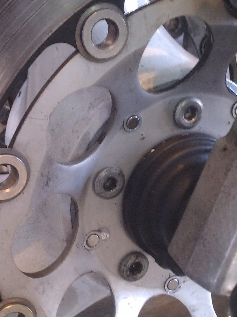
I just remeasured my 08-09 rotor buttons with a micrometer and the inside diameter was 11mm for the middle part and 12mm on the shoulder (not that your will be the same as mine). Also I thought to 06 750 had 8 buttons, do you have aftermarket rotors?
My paint skill aren't the best but to show you how I measured mine and the red area is where I will probably have to remove about .35mm off each side to make the 1/2" cups fit since they should be about 12.7mm.
![Image]()
My paint skill aren't the best but to show you how I measured mine and the red area is where I will probably have to remove about .35mm off each side to make the 1/2" cups fit since they should be about 12.7mm.
Attachments
-
 11.2 KB Views: 1,281
3,287 posts
·
Joined 2009
This is the rotor that I have.
http://cgi.ebay.com/ebaymotors/2007...-FRONT-ROTOR-/200595130631?pt=Motorcycles_Parts_Accessories&hash=item2eb466c907
-
I bought the bike with the front end already installed, so bear with me...
http://cgi.ebay.com/ebaymotors/2007...-FRONT-ROTOR-/200595130631?pt=Motorcycles_Parts_Accessories&hash=item2eb466c907
-
I bought the bike with the front end already installed, so bear with me...
16 posts
·
Joined 2011
I need some help with this as well.
Info:
1993 GSXR750 front end
Sensor - Cherry GS101201 Gear tooth sensor
5 magnets drilled into rotor evenly spaced
magnets are 3" from axle
So I cant get any reading on my speedo at all. I have tried both sides of the magnet (attracting / opposing).
Can someone tell me what I am doing wrong? What spacing do I need for accurate readings? Correct number of magnets?
Thanks in advance!
![Image]()
![Image]()
Info:
1993 GSXR750 front end
Sensor - Cherry GS101201 Gear tooth sensor
5 magnets drilled into rotor evenly spaced
magnets are 3" from axle
So I cant get any reading on my speedo at all. I have tried both sides of the magnet (attracting / opposing).
Can someone tell me what I am doing wrong? What spacing do I need for accurate readings? Correct number of magnets?
Thanks in advance!
-
?
-
?
-
?
-
?
-
?
-
?
-
?
-
?
-
?
-
?
-
?
-
?
-
?
-
?
-
?
-
?
-
?
-
?
-
?
-
?
- posts
- 2.5M
- members
- 80K
- Since
- 2002
A forum community dedicated to Suzuki SV650 owners and enthusiasts. Come join the discussion about performance, modifications, racing, troubleshooting, maintenance, and more!
Top Contributors this Month
View All
Slowhands
381 Replies
Straticus
130 Replies
Troy Jollimore
101 Replies


